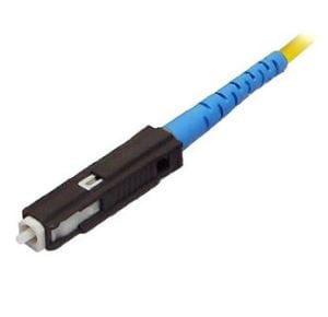
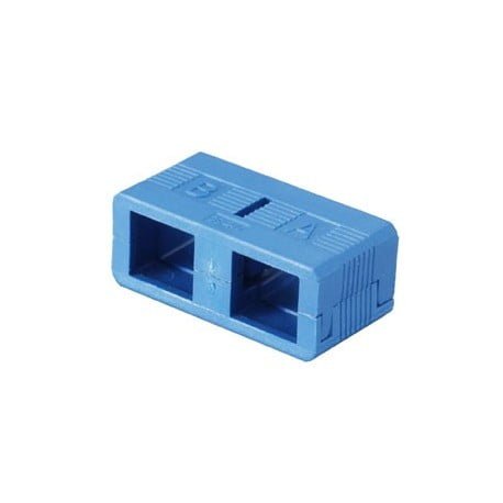
MU Optical Fiber Connector An optical fiber connector terminates the end of an optical fiber, and enables quicker
connection and disconnection than splicing
MU Optical Fiber Connector An optical fiber connector terminates the end of an optical fiber, and enables quicker
connection and disconnection than splicing. The connectors mechanically couple and align the cores of fibers so
light can pass. Better connectors lose very little light due to reflection or misalignment of the fibers.MU is a
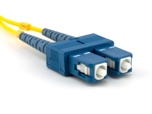
small form factor SC. It has the SAME push/pull style, but can fit 2 channels in the same Footprint of a single
SC. MU was developed by NTT.The MU Connector looks a miniature SC with a 1.25 mm ferrule. It is a popular
connector type in Japan.
singlemode and multimode MU connectors and adapters are fully intermateable with NTT-MU style products, and are
NTT and JIS compliant.* This small form factor connector is approximately half the size of the SC connector, and
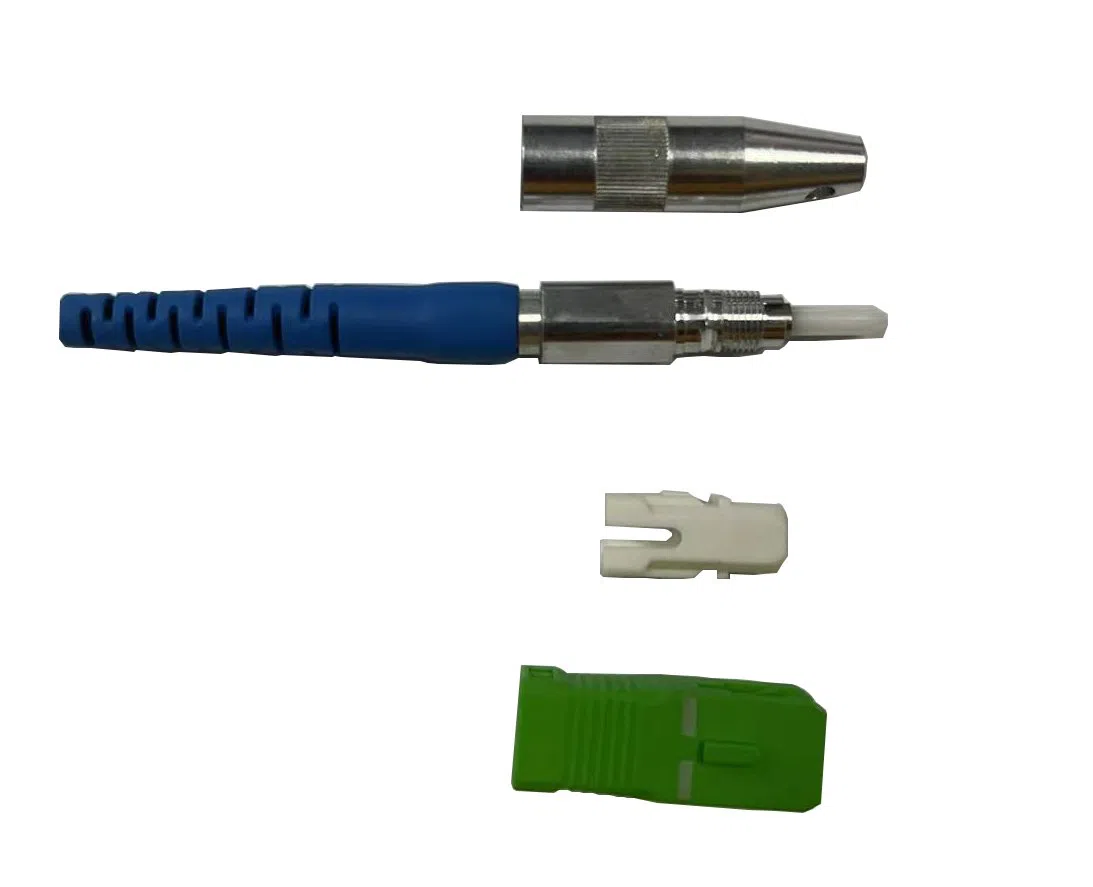
has a push-pull style design. The connector features a pre-assembled body and precision molded plastic housing,
and a freefloating ferrule measuring 1.25mm O.D. held in place with a precision spring.
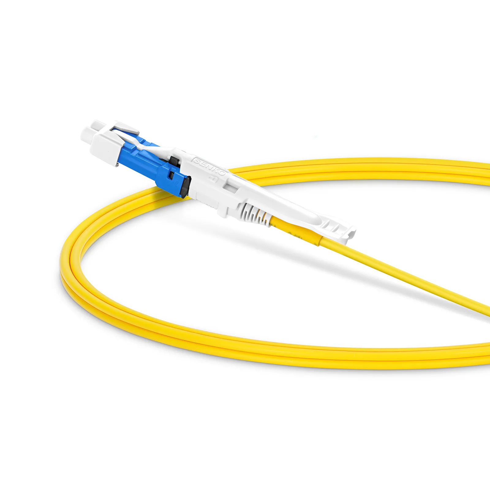
Housing and boot are made from UL-rated material. The MU-J style connector is the same as the regular MU
connector, but without the outer housing, and with a very narrow, short boot for 900 micron fiber, ideal for
back panel solutions and high-density situations.
The MU connector features a pre-assembled body, with square shape and a push-pull latching for easy operation.
This MU connector is approximately half the size of the normal ST/SC connector, which is ideal for high-density
situations.
MU connectors and adapters were developed by NTT, and have push-pull function. The connectors are composed of
plastic housing and φ1.25mm Zirconia Ferrules. These products, called as “mini SC,” have high reliability and
operationally same with SC connectors and adapters. MU connectors are the optical connectors which miniaturized
and were advanced the density application and performance.
Because we are a specialty manufacturer of precision ferrules, easy fiber insertion, precision polish process,
and high quality of the connectors are realized. There is no need to change the condition of the assembling and
polishing of the ferrules because we can continue to supply completely same ferrules at the same quality level
at anytime.
High optical performance
Insertion Loss: ≤0.3dB
Operation temperature: -40℃ ~ 85℃
High Return Loss: ≥60dB
Insert-pull test: 500 time, <0.3dB
A variety of options
Mold
Type
Cable
Housing Color
Boot Color
SM
Simplex
0.9mm
Green
Green
MM
Duplex
2.0mm
Blue
Blue
Beige
Beige
Brown
Brown
White
Items
Single mode
Multi mode
Insertion Loss
≤0.3dB
≤0.3dB
Return Loss
≥50dB(UPC);≥60dB(APC)
≥30dB
Ceramic ferrule spec
125.5um concentricity deviations:(<)1um< /td>
127um concentricity deviations:(<)3um< /td>
Insert-pull test
500 times (<)0.3dB< /td>
Operation temperature
-40℃ ~ +85℃
Suitable fiber
PC/APC(9/125um)
PC(50/125um,62.5/125um)
Construction Details
Ferrule Material: Precision zirconia ceramic ferrule, 1.25 mm diameter
Housing Material: Thermoplastic polymer compliant with RoHS
Polish Type: UPC or APC
Fiber Type: Singlemode (G.652D/G.657A1) or Multimode (OM1-OM3)
Boot Type: 0.9 mm, 2.0 mm, or 3.0 mm fiber cable options
Coupling Mechanism: Push-pull latch system for quick connection and disconnection
Transmission Properties:
Fiber Type
SM 9/125um
(1310nm/1550nm)
62.5um (OM1)
(850nm/1300nm)
50um (OM2)
(850nm/1300nm)
50um (OM3)
(850nm/1300nm)
Maximum Attenuation (dB/km)
0.8/0.6
3.5/1.5
3.5/1.5
3.5/1.5
Typical Attenuation (dB/km)
0.4/0.3
3.5/1.5
3.0/1.0
3.0/1.0
Minimum LED Bandwidth (MHz·km)
—
200/500
500/500
1500/500
Features:
Crush resistance and flexibility
Good mechanical and temperature performance
PE sheath protects cable from ultraviolet radiation
High strength loose tube that is hydrolysis resistant
Special tube filling compound ensure a critical protection of fiber
Specially designed compact structure is good at preventing loose tubes from shrinking
The following measures are taken to ensure the cable watertight:
2D: SM G.652.D
7A1: SM G.657.A1
7A2: SM G.657.A2
7B2: SM G.657.B2
7B3: SM G.657.B3
OM1: MM 62.5/125um
OM2: MM 50/125um
OM3: MM 10G 50/125um
OM4: MM 10G 50/125um